Crimping Pliers join wires, terminals, and connectors by compressing a fitting around a conductor. The result should feel firm, sit evenly, and resist pulling loose. In a workshop, that may mean matching a terminal to the wire, placing it squarely in the correct jaw, then squeezing the handles until the connection is secure. Small details matter.
Crimping Pliers are not one-size-fits-all tools. Different models serve insulated terminals, non-insulated terminals, ferrules, or specialized connectors. The correct tool depends on the connector and wire specifications. A mismatched jaw can leave a crimp that looks neat but performs poorly. It’s easy to overlook.
A reliable guide should explain how to choose the tool, prepare the wire, position the connector, and inspect the finished crimp. It should also be honest about limits: appearance alone cannot prove a connection is sound. I can’t verify a real expert’s name or quotation from the information provided, so I won’t invent one. A sourced expert comment would strengthen this introduction and support its practical advice.
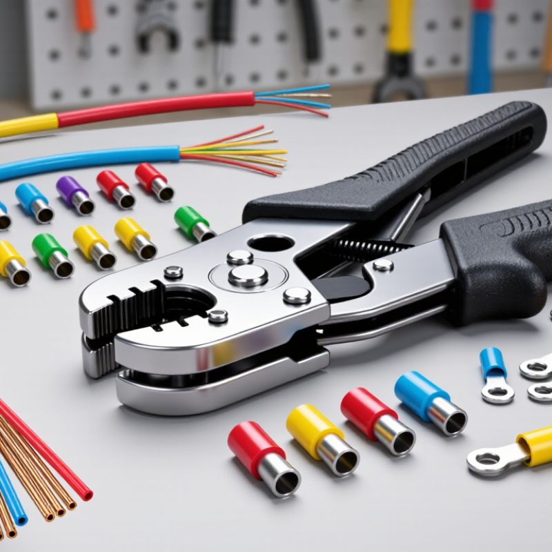
Crimping pliers join a wire to a compatible terminal by squeezing the metal barrel around the conductor. The tool’s shaped jaws apply pressure at a specific point, deforming the barrel so it grips the wire strands. Done well, the connection conducts electricity and resists ordinary pulling. No solder is needed.
A proper fit matters. Match the tool’s crimping slot to the terminal and wire size; a loose crimp may slip, while excessive pressure can damage strands. Strip only enough insulation to expose the conductor, then seat the wire fully inside the terminal barrel. Squeeze the handles firmly. Some tools release only after completing a full cycle, which helps produce consistent crimps, though it cannot correct a mismatched terminal. Check the finished joint for exposed loose strands, cracks, or a crooked barrel. Give the wire a gentle pull. It should stay put. I’ve found that rushed crimps can look tidy but still fail under strain, so visual inspection alone is not enough. The right tool also depends on the job: small insulated terminals, open-barrel contacts, and larger cable lugs may need different jaw shapes. If the connection feels uncertain, redo it with a fresh terminal rather than trusting a questionable squeeze.
Crimping pliers join a wire to a terminal, connector, or cable lug by compressing the connector barrel around the conductor. The chart shows common copper conductor sizes used with crimp-style electrical terminals.
Conductor areas are standard approximate cross-sectional equivalents for common AWG sizes. Always match the crimp die and terminal to the connector manufacturer's specified wire range.
What Are Crimping Pliers Used For?
Key Applications of Crimping Pliers in Electrical and Mechanical Tasks
Crimping pliers form a secure joint by compressing a terminal or sleeve around a conductor. In electrical work, they attach terminals to wires for control panels, appliances, and vehicle wiring. Match the tool and die to the terminal type and wire gauge. Strip only the required length, seat the conductor fully, then inspect the crimp for gaps, loose strands, or damaged insulation. Fit matters. A neat-looking joint can still be poorly seated, so visual inspection alone is not enough.
In mechanical tasks, purpose-built crimpers secure ferrules on control cables and sleeves on compatible wire-rope assemblies. These joints help keep cable ends tidy and reduce slippage under load. Do not assume one crimper suits every material or fitting; use the specified tool and follow the fitting maker’s instructions. NFPA’s Home Electrical Fires report recorded an annual average of 32,620 U.S. home structure fires involving electrical distribution or lighting equipment from 2015 to 2019. That figure does not mean crimping prevents such fires, but it underlines why careful electrical work matters. When a connection will carry current or load, check it with the appropriate pull or continuity test. Small detail. A rushed crimp can be difficult to spot later.
Crimping pliers join a wire to a terminal by pressing the metal sleeve around the conductor. The right tool depends on the connector, wire size, and crimp shape—not just how sturdy the pliers feel.
Insulated-terminal crimpers are suited to common pre-insulated ring, fork, and spade terminals. Their color-coded or marked dies help match the terminal size, but always check the tool’s specifications. Non-insulated-terminal crimpers make tighter metal-to-metal crimps on bare terminals, often used in repair or control-panel wiring. Open-barrel crimpers shape the small tabs found on many automotive and electronic connectors. Those tabs grip both the conductor and its insulation. Fit matters. A crimp can look neat and still be weak.
Ferrule crimpers compress tubular sleeves onto stranded wire, keeping loose strands together before insertion into a screw terminal. Coaxial compression tools are made for compatible coax connectors and apply even pressure around the cable. For thick cable or large lugs, hydraulic crimpers provide greater force, while compact ratcheting models suit repeated terminal work. Not interchangeable. The terminology can be confusing, and die markings are easy to misread. Check the connector maker’s wire range, choose the matching die, then test a sample crimp and inspect it for a secure hold.
Crimping pliers join a wire to a compatible terminal by compressing the metal sleeve around it. A dependable crimp needs the right tool, terminal, and wire size. Before starting, disconnect the circuit and verify it is not live with a suitable tester. Wear eye protection; short wire offcuts can flick away unexpectedly.
Strip only the length specified for the terminal. Avoid nicking or cutting strands, since damaged wire can weaken the connection. Match the terminal to the wire gauge, then select the corresponding crimper die. Insert the wire fully, with insulation positioned as the terminal design requires. Keep your fingers clear of the jaws and squeeze the handles through a complete cycle. Don’t guess at the die size. The fit can look close and still be wrong.
Inspect the finished crimp for cracks, loose strands, or exposed conductor where it should be covered. Give the wire a firm, gentle pull; it should not slide out. A neat-looking crimp alone proves little. If it shifts, cut it off and make a new connection with fresh terminal material. It is easy to rush this step, especially on a small repair, but pausing to check the fit is worthwhile. Follow the terminal’s instructions whenever strip length or crimp position is unclear.
Crimping pliers join a terminal to a wire by compressing the metal barrel around the conductor. Choosing the right tool starts with the terminal and wire, not the handle. Check the specified wire-size range, terminal type, and die profile. A mismatch can leave loose strands, a crushed barrel, or a connection that looks sound but fails under load. Small details matter.
For controlled work, consider a ratcheting tool that cannot release before completing its cycle. The feature helps produce repeatable crimps, though it does not replace inspection. IEC 60352-2:2020 covers requirements and tests for crimped electrical connections; its framework supports checking the connection, not relying on appearance alone. Match the die to the connector’s stated requirements, then inspect sample crimps and perform the prescribed pull test where applicable. There is no universal pull-force value: it depends on conductor size and connector design.
Comfort and maintenance count, too. Squeeze the handles several times before buying; sharp edges or excessive opening force become tiring during repetitive work. Check whether dies are replaceable and whether the tool can be calibrated. A worn die can make a familiar task unreliable. I would still keep a simple log of inspections—easy to overlook, but useful when results start drifting.
| Common Use | Typical Connector or Terminal | Typical Wire Range | Recommended Crimping Tool Profile | Important Selection Factors | Expected Result |
|---|---|---|---|---|---|
| Attaching insulated terminals | Insulated ring, fork, and butt connectors | Approximately 22–10 AWG (0.5–6 mm²) |
Color-coded die cavities matched to the terminal size | Correct terminal color range, wire gauge capacity, die accuracy, and ratcheting action | A mechanically secure connection with a properly compressed terminal barrel |
| Installing non-insulated terminals | Uninsulated ring, spade, and butt terminals | Approximately 22–8 AWG (0.5–10 mm²) |
Precise non-insulated terminal crimper with shaped dies | Terminal material, conductor-barrel size, crimp profile, and access to confined spaces | Firm metal-to-metal contact without excessive deformation |
| Joining wires with butt connectors | Insulated or heat-shrink butt splices | Approximately 22–10 AWG (0.5–6 mm²) |
Parallel or oval crimp cavities designed for splice barrels | Compatibility with heat-shrink tubing, jaw width, applied force, and strain relief | A low-resistance splice that resists wire pull-out |
| Crimping wire ferrules | Bootlace ferrules for stranded wires | Commonly 0.5–6 mm² | Square, hexagonal, or trapezoidal ferrule crimper | Ferrule cross-section, conductor size, crimp geometry, and compatibility with terminal blocks | Strands remain bundled for easier insertion and reliable screw-terminal contact |
| Terminating open-barrel contacts | Open-barrel terminals used in wiring harnesses | Varies by terminal design; commonly 20–10 AWG | Dedicated open-barrel crimper with conductor and insulation wings | Terminal dimensions, wing height, conductor support, and tool alignment | A controlled “B-crimp” or manufacturer-specified profile with supported insulation |
| Connecting coaxial cable ends | Coaxial connectors with crimp sleeves | Common cable sizes include RG-58, RG-59, and RG-6 types | Coaxial crimper with size-specific hex cavities | Cable diameter, connector sleeve size, impedance system, and die dimensions | A secure shield and jacket connection while maintaining cable geometry |
| Installing modular data plugs | RJ-type modular plugs for twisted-pair cable | Commonly used with solid or stranded data cable of compatible diameter | Dedicated modular-plug crimp tool with contact-seating and cable-cutting functions | Plug type, conductor arrangement, cable diameter, strain-relief design, and cutting quality | Contacts are pressed evenly into the conductors and the cable is held securely |
| Preparing solar or power connectors | Specialized photovoltaic or high-current power contacts | Often approximately 2.5–6 mm², depending on the connector | Connector-specific precision crimper | Contact dimensions, current rating, conductor size, tooling tolerances, and environmental sealing | A repeatable crimp suitable for outdoor, vibration, and moisture-exposed installations |
| Repairing automotive wiring harnesses | Sealed and unsealed automotive terminals | Commonly 20–10 AWG (0.5–6 mm²) |
Automotive terminal crimper matched to the terminal series | Seal compatibility, terminal material, conductor-wing shape, vibration resistance, and reach | A compact connection that maintains electrical and mechanical integrity under vibration |
| Creating battery and high-current cable connections | Heavy-duty copper lugs and tubular cable terminals | Often approximately 6–2/0 AWG (16–70 mm²) |
Heavy-duty ratcheting, hydraulic, or mechanical lug crimper | Cable cross-section, lug barrel length, required compression force, portability, and repeatability | A low-resistance joint capable of carrying the intended current when correctly sized |
Crimping pliers join wires to compatible terminals by compressing a metal barrel around the conductor. No solder is required. They also secure ferrules and suitable cable sleeves in mechanical work.
Shaped jaws apply pressure at a specific point. The terminal barrel deforms around the wire strands. This grip supports electrical conduction and ordinary pulling resistance.
Match the jaw slot, terminal type, and wire gauge. Small insulated terminals, open-barrel contacts, and larger lugs need different jaw shapes. One tool rarely fits everything.
Strip only enough insulation to expose the conductor. The wire should sit fully inside the terminal barrel. Too much exposed metal can create a weak or unsafe joint.
Look for loose strands, cracks, gaps, or a crooked barrel. Then give the wire a gentle pull. It should remain firmly attached. Visual inspection alone is not enough.
Excessive pressure can damage wire strands or distort the terminal. A loose crimp may slip. The correct pressure depends on the matching tool and fitting.
Some tools release only after the handles complete their cycle. This encourages consistent compression. However, it cannot fix the wrong terminal or wire size.
Remove it and use a fresh terminal. Do not trust a questionable squeeze. I have learned that rushed crimps can look neat but fail under strain. A proper pull or continuity test adds confidence.
Crimping Pliers are hand tools designed to join wires, terminals, and other compatible components by pressing them together to form a secure connection. They work by applying controlled pressure through shaped jaws, helping create reliable electrical connections and firm mechanical fastenings. Depending on their design, they may be suited to insulated or uninsulated terminals, cable ends, connectors, or other specific materials and sizes.
For safe, effective results, choose a tool that matches the connector, wire gauge, and task. Position the materials correctly in the appropriate jaw, then apply steady pressure without forcing the tool or damaging the parts. Inspect the finished crimp to confirm that it is secure and properly formed. Considering the tool’s crimping range, jaw design, ease of use, and intended applications can help you select the right pair for electrical or mechanical work.